

Die casting mold design guidelines
Die casting is a manufacturing process that are used to produced metal parts in various industries, specially for high volume production requirements, but to make die casting parts, the is one important cost is to make die casting mold, or we call die casting tooling, and the die casting mold cost is normally very high, specially high pressure die casting mold, such as aluminum die casting mold, magnesium die casting mold, zinc die casting mold, and copper die casting mold.
The die casting mold is a precisely tool that could produce 100 thousands die casting parts or even more, and the most important factor to affect the die casting mold life is steel and the mold design, today we will discuss about die casting mold design guidelines here, if you want to know more about die casting mold steel, please go to die casting mold page to know more.
In order to be able to think in the same way within our die casting mold manufacturer, and to be able to use layout dimensions that are suitable for all applications we have created the following die casting tooling design guidelines. Design layout and the dimensions are important factor to last die casting mold life. Those guidelines will be used by the calculation engineers as well as a base for the die casting mold designers during die design.

1. Injection gate and overall layout.
- Generally the injection gate will be placed along the longest side of the part and the injection gate cylinder will be on the closest distance to that side (runner will normally not go around the cavity like a banana).
- If sliders are used or if other factors may influence the placement of the injection gate or runner ask the customer what they recommend in each case. Agree with a solution before the die casting mould design starting. Then the general layout will be suitable for almost all dies.
2. Distance between the cavity edges and the insert edges.
- For normal cases, except for die casting moulds with bigger sliders or “deep” parts, use the distance 60-80mm. The upper limit is used for “bigger” parts and the lower limit is for smaller parts.
- For die casting moulds with bigger sliders the distance can be up to 90-100mm, especially when it concerns the two sides to right and left from the slider side.
- For really deep parts the distance may be bigger than 100mm, but then we should ask the customer for advice before starting die casting mold design.
- For really small parts the minimum distance of 50mm is used.
- The distance for the side towards the injection cylinder is the same as for the other sides, but about 10-15mm on top of that.
3. Distance between cavities.
- Generally a distance of 60-80mm is used for most cases.
- For really small parts the distance of a minimum 45-50mm is used.
- For really deep parts the distance is generally bigger than 80mm, but then we should ask the customer for advice or provide them our suggestions.
- For cases when the runner is between the cavities the distance will be increased with 30-40mm on top of what the distance would have been without the runner.
4. Distance between the edge of the insert and the edge of the mould base.
- Generally (for normal cases) the guide is to use the same distance as what is used for injection moulding (as long as the part do not require big sliders). That includes bigger parts, deeper parts and parts requiring smaller sliders. That means a distance of 60-90mm is OK for most die casting moulds.
- For die casting tooling with big hydraulic sliders there is a need to increase the distance with 50-200mm on top of the normal distance (more than what would have been needed for injection moulding). However, for those cases we should ask the customer for advice or providing our deign suggestion and ask customer approval. One question is also how asymmetrical the die casting mould can be in case a big slider is only used on the right or left side of the die.
5. Thickness of A/B plates and inserts.
- The thickness for both the inserts and A/B plates are mainly controlled by the projected area. As a rule of thumb thicknesses specified in below table will be used when designing die casting moulds. The projected areas are specified in cm2. For big projected areas or deep die casting molds it is recommended to ask the customer for advice, or provide some suggestions for customer selecting.
|
Projected area (cm2) |
Thickness between insert edge and backside of A/B plate |
Thickness between cavity edge and backside of insert edge |
||
|
A-plate |
B-plate |
Insert-A |
Insert-B |
|
|
1-100 |
35-40 |
40-45 |
35-40 |
38-40 |
|
100-300 |
40-60 |
45-70 |
40-45 |
40-45 |
|
300-600 |
60-80 |
70-100 |
45-50 |
45-55 |
|
600-1000 |
80-110 |
100-130 |
50-60 |
55-65 |
|
1000-1500 |
110-140 |
130-160 |
60-65 |
65-70 |
|
>1500 |
≥140 |
≥160 |
≥65 |
≥70 |

Die Casting Mold Design Checking List
Below is our die casting mold design checking list, for every single die casting mold, we will check below item one by one before die manufacturing:
Casting drawing:
- Product shrinkage: Make sure that we have added the shrinkage rate in the die design
- Check if the product ratio is 1:1, and check with the customer’s 2D drawing overall size.
- Check if the draft angles have added correctly.
- Check and adjust 3D tolerances according to customer’s 2D product drawings (if have tight tolerance)
- Read the drawing and check the information prompts in the customer’s 2D drawing.
- Double check the casting part drawing is the latest version
- Make is if Radius can be added to all positions, and the size needs to be as shown in the 2D casting drawing.
Mold base:
- When the mold base needs to be manually corrected, whether it is in accordance with the LKM standard (must be particularly careful if they are inverted die casting mold, the front or rear mold has spring plates, and the mold base with pushing plate etc.).
- Make sure the Mold base guide system is designed according to customer requirements. If no requirement we can follow with LKM guide system.
- The size of the mold base guide pillars should not exceed 40-50MM, especially for large die casting molds.
- The length of the mold base guide pillar can only be 20-30mm longer than the height of the B plate ( Pass through B plate 20-30mm).
- The square supporting bar in the mold base needs to be on all sides, and the supporting bar needs to be fixed on the bottom plate.
- Need to use graphite guide bushing for the ejector guiding system (graphite guide bushing on the ejector plates).
- Stop pins need to be added under the bottom plate of the ejector pins. Basically, it is necessary to ensure that there are stop pin under each ejector pin.
- Pry bar score needs to be added around the mold base, the minimum size is 40X25mm.
- Make sure there are lifting holes on all four sides of mold base.
- When lifting the fixing half and moving half of die casting mold, need to ensure that that lift each half mold in the center alone.
- Need to have locking block on the die casting mold
Die casting mold structure:
- When the customer has structural suggestions, the customer’s plan is preferred.
- Make sure the slide travel distance is sufficient.
- Double check that the die casting mold opening steps for the entire set of molds are OK (be especially careful with complex structures).
- The size of cooling channels are as per customer’s request.
- The screw thread size of the cooling channels needs to be according to the customer’s standards and needs to be marked on the manufacturing of die casting mold drawing.
- The Knockout position must match the customer’s machine, as well as the mold trial machine.
- The sprue sleeve is sized according to customer requirements, tolerances need to be marked and need to match the die casting machine.
BOM list:
- Check if designed with current steel for Mold core and cavity, and sliders, and hardness should be according to customer requirements.
- There should be a difference in hardness between sliders and cores.
- Mold components should be according to customer requirements, HASCO, DME or any other specified tool components.
- Make sure all of quality of components are correctly.
In Summrize:
Die casting mold design is a key point to make high quality die casting mold, wrong design will break the die casting mould very fast or even breaking at mold trial stage, if you have a die casting project in handles that need to make a die casting mold and casting parts, we suggest you find a professional die casting tooling manufacturer, if you are die casting manufacturer and looking for die casting mold design, then we suggestion find a professional die casting mold manufacturer as well, becaue those die casting tooling manufacturers are professional in design and manufacturing dies.
If you do not mind, you are welcome to contact and send us your die casting project, we will quote you a price for your refernece.
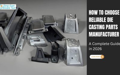
We are one of top 10 aluminum die casting manufacturers in China, we offer custom die casting molds, die casting parts, machining parts, prototyping parts, surface finish, polishing, assembly, and delivery services.![]()

0 Comments