
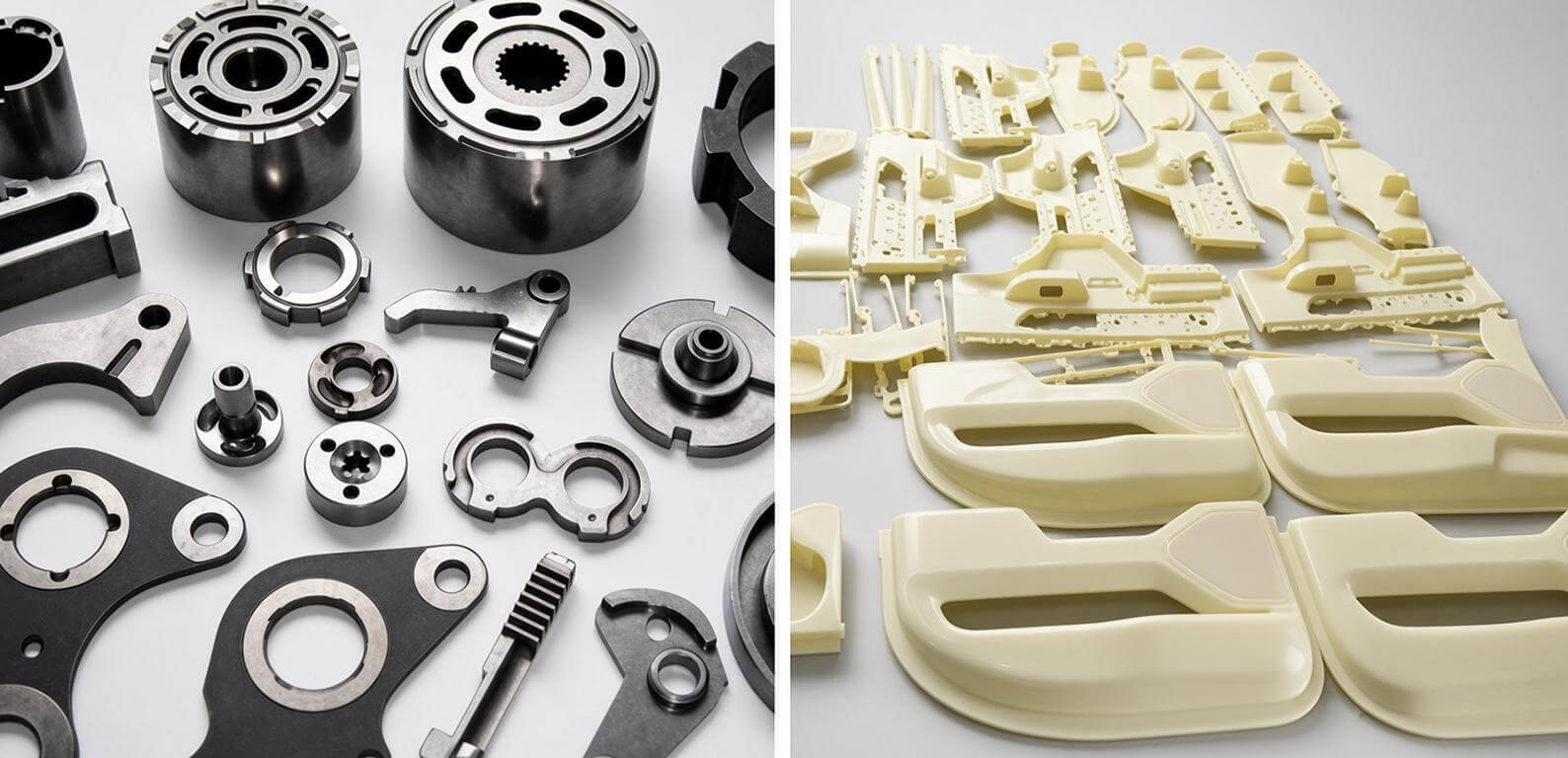
Before you commit tens of thousands of dollars to an injection mold or a die casting die, you need to know that the part works. Snabb prototyptillverkning (RP) gives you a physical part from a CAD file in hours or days, so errors are found on a bench instead of on a production tool.
This guide explains what rapid prototyping is, how the main technologies compare, what each is good for, and how to move from a 3D printed prototype to a trial mold and then to mass production. It ends with an engineering checklist you can adapt to your own program.
What Is Rapid Prototyping?
Rapid prototyping is the fast fabrication of a physical model or part directly from 3D CAD data. Most RP processes are additive: material is added and bonded layer by layer, which is why the field is also called layered manufacturing or additive manufacturing. 3D printing is the common name for the same family of processes.
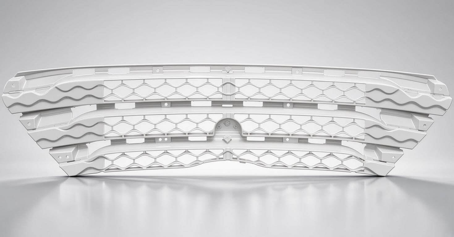
It helps to separate three types of fabrication:
- Subtractive: start with a solid block and remove material (CNC milling, turning, grinding).
- Additive: build the part by adding material (stereolithography, laser sintering, filament extrusion).
- Formative: shape material with force or a mold (forging, injection molding, die casting).
Stereolithography (SLA), patented in the 1980s, started the RP industry. Today the term also covers rapid CNC machining, because a machined prototype from billet is often the fastest way to get a functional metal part.
How Rapid Prototyping Works
Most additive processes follow the same data flow:
- Build the 3D CAD model (solid or surface).
- Export it as an STL file, a mesh of triangles that approximates the surface.
- Check and repair the mesh (gaps, flipped normals, non-manifold edges).
- Choose orientation and generate supports for overhangs.
- Slice the model into thin layers.
- Build the part.
- Remove supports and clean the part.
- Post-process: cure, sand, bead blast, paint, or machine critical features.
Two practical points matter for engineers. First, a coarse STL shows facets on curved surfaces, so export with a tolerance that matches the accuracy you need. Second, build orientation changes strength, surface finish and dimensional accuracy, because layered parts are anisotropic.
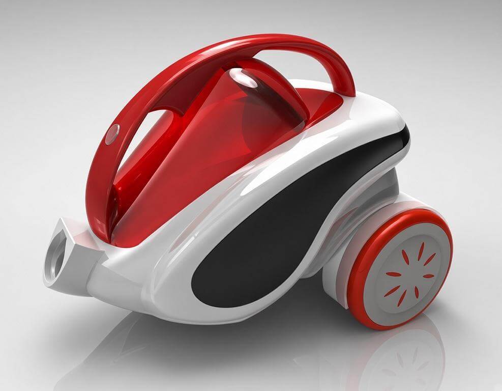
Main Rapid Prototyping Technologies Compared
| Process | Typical materials | Typical strengths | Typical limits |
|---|---|---|---|
| SLA (photopolymer resin, laser cured) | Epoxy, acrylate and urethane resins | Smooth surface, fine detail, layer about 0.05 to 0.1 mm | Brittle or UV-sensitive resins; needs post-cure |
| SLS / powder bed fusion (polymers) | Nylon (PA12, PA11), glass-filled nylon | No support structures, tough functional parts | Grainy surface, shrinkage on large parts |
| FDM / filament extrusion | ABS, PLA, PC, nylon | Low cost, easy to use, good for fit checks | Visible layer lines, anisotropic strength, lower accuracy |
| Material jetting | Photopolymers, multi-material | Fine detail, color and soft-touch options | Material cost, limited heat resistance |
| Metal powder bed fusion (DMLS/SLM) | AlSi10Mg, stainless steel, titanium | Complex metal geometry, functional metal prototypes | High cost; surface and porosity differ from die cast |
| Rapid CNC machining | 6061, 7075, plastics such as ABS, POM, PC | Tight tolerances, production-like surfaces | Cost rises with complexity; undercuts need multi-axis |
Typical dimensional accuracy for desktop and industrial polymer processes is in the range of a few tenths of a millimeter, and a published SLA study reports about 0.1 mm for well-controlled builds. CNC machining typically holds ±0.05 mm or better. Always confirm capability with the service provider for your part size and material.
What Is Rapid Prototyping For?
Rapid prototyping is used wherever a physical part answers a question faster or cheaper than analysis or tooling.
Design visualization and communication. People understand a physical model faster than a drawing. A case reported in the literature found that giving vendors RP models reduced quoted prices, because suppliers were more confident about what they were bidding on.
Fit and assembly checks. A printed part exposes misaligned holes, interference and wrong mating geometry that are easy to miss on a screen.
Verification of CAD data. Rib positions, snap-fit clearances and wall thickness problems show up immediately.
Functional and ergonomic testing. Housings, handles, brackets and wearable products can be tested by hand before tooling.
Feedback from toolmakers and casters. A tool designer often suggests small changes (draft, parting line, coring) that reduce tooling cost, and a physical part makes that conversation concrete.
Patterns and tooling. Printed wax or resin patterns can be used for investment casting, and prototype or bridge molds can be made quickly for small batches.
Low-volume production and fixtures. Jigs, fixtures and gauges are often printed in-house to save machining time.
Prototype Fidelity: Choose the Right Level
Not every prototype needs to match the production part. Matching the fidelity to the question saves time and money.
| Level | Question it answers | Typical method |
|---|---|---|
| Concept model | Does the shape and size feel right? | FDM or SLA |
| Form and fit | Does it assemble and clear neighboring parts? | SLA, SLS, rapid CNC |
| Functional | Does it carry load, seal, dissipate heat? | SLS nylon, machined metal, DMLS |
| Pre-production | Does the production process make it correctly? | Trial mold or die samples |
A printed ABS-like part cannot prove that a glass-filled nylon part will survive a drop test, and a machined 6061 bracket cannot prove that an A380 die casting is free of porosity. Be explicit about what each prototype does and does not validate.
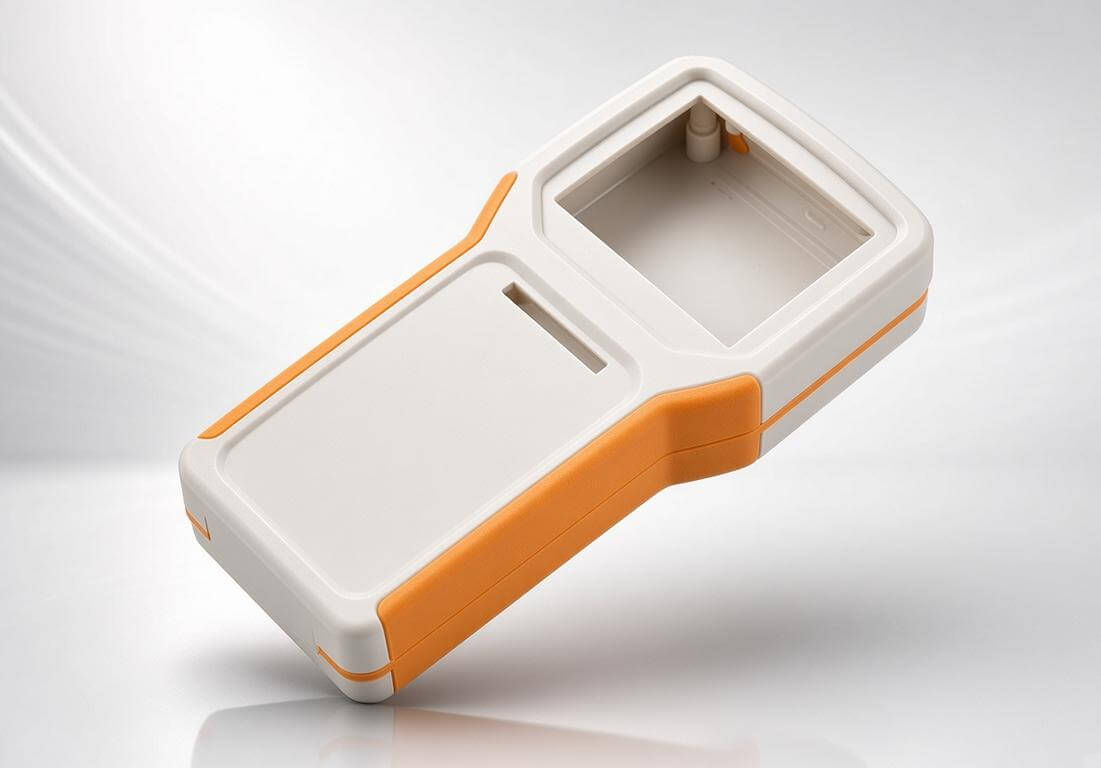
Rapid Prototyping for Injection Molding
Prototypes help most before the mold is cut, because steel changes are slow and expensive.
What prototypes validate: assembly, snap fits, living hinge geometry, boss and rib layout, appearance, and early user feedback.
What they do not validate: resin shrinkage and warpage, weld lines, gate vestige, sink marks, fill balance, and the effect of glass fiber orientation. These depend on the actual resin and process.
Use the prototype round to correct the design rules that govern molded parts:
- Keep wall thickness as uniform as practical, commonly about 1 to 3 mm for many thermoplastics.
- Add draft, typically 0.5 to 2°, more on textured surfaces.
- Keep ribs at roughly 50 to 60% of the adjacent wall to limit sink marks.
- Use generous radii instead of sharp corners.
- Plan the gate location and parting line early.
When volumes are modest, an aluminum prototype or bridge mold (for example 7075 aluminum) can reduce tooling lead time and allow real molded samples in the target resin, while production molds use hardened steel such as P20, H13 or stainless 420 depending on resin and volume.
Rapid Prototyping for Die Casting
Die casting has no cheap equivalent of a printed mold, so prototype strategy matters.
Common routes for aluminum die cast prototypes:
- CNC machining from billet (often 6061 or similar): fast, accurate, good for form, fit and function. Strength and thermal properties differ from A380 or ADC12.
- Metal 3D printing (AlSi10Mg powder bed fusion): complex shapes without tooling, with properties and porosity that differ from die cast material.
- Investment or sand cast from a printed pattern: gives a cast structure for small quantities.
- Soft or single-cavity prototype die: closer to production, with higher cost.
What prototypes validate: geometry, assembly, machining datums, sealing face layout, wall thickness and boss design.
What they do not validate: filling pattern, gas and shrinkage porosity, thermal balance in the die, soldering, flash, and mechanical properties of the as-cast skin. Use casting simulation and a proper trial to address these.
Design for high pressure die casting at the prototype stage: uniform walls (about 1.5 to 4 mm), draft (about 1 to 3°), generous fillets, ribs at or below wall thickness, and machining stock on critical faces (commonly 0.3 to 0.8 mm).
Benefits and Limitations
Fördelar
- Shorter development cycles and earlier error detection.
- Geometry freedom with no tooling.
- Lower cost per iteration at low quantity.
- Better communication between design, tooling and supply chain.
Begränsningar
- Materials and properties differ from production resin or alloy.
- Accuracy, surface finish and detail are generally lower than molded or cast parts.
- Cost per part does not fall with volume, and the advantage shrinks as part size grows.
- Layered parts are anisotropic.
From 3D Printed Prototype to Trial Mold to Mass Production: Engineering Checklist
Use this phase-gate checklist to move from first print to stable production. Each phase has an exit criterion that should be signed off before spending on the next.
| Phase | Key actions | Exit criterion |
|---|---|---|
| 1. Requirements | Define function, loads, temperature, chemicals, annual volume, target cost, critical-to-quality (CTQ) dimensions, cosmetic zones, and candidate material | Signed requirements and CTQ list |
| 2. Concept prototype | Print SLA or FDM models, review shape and size, check CAD errors, share with the toolmaker or caster | Design intent confirmed |
| 3. Fit and functional prototype | Use SLS nylon, rapid CNC or DMLS; run assembly, load, thermal and sealing tests; record correlation to production material | Functional tests passed and documented |
| 4. DFM and simulation | Review draft, walls, ribs, radii, parting line, gate and ejector locations; run mold-flow or casting simulation; do tolerance stack-up; add machining stock | DFM report closed, 3D data frozen under change control |
| 5. Tool design | Select steel (P20, H13, 420 stainless for molds; H13 for dies), plan cooling or thermal management, venting, inserts, slides; build gauges and fixtures | Tool design review signed |
| 6. Trial (T0/T1) | Run first shots; for molding, study short shots and fill balance; for die casting, tune shot profile and die temperature; measure with CMM; X-ray castings | Sample report and tool correction list |
| 7. Tool correction and validation | Adjust steel, run T2, set the process window with a design of experiments, run capability study (Cpk) on CTQs, first-article inspection, leak or functional tests | Approved samples and validated process |
| 8. Pilot and ramp-up | Run a pilot lot, confirm cycle time, scrap rate, packaging and traceability, start SPC | Pilot yield and capability meet target |
| 9. Mass production | Apply control plan, preventive tool maintenance, periodic audits, and change management | Stable, monitored production |
Additional Checks for Injection Molding
- Confirm shrinkage assumptions with the resin supplier, noting that shrinkage differs along and across flow, especially in glass-filled grades.
- Verify gate type, vent depth and land length against the resin, since vent depth varies widely between resins.
- Check cooling circuit layout and water temperature to control warpage and cycle time.
- Size the press with clamp force based on projected area and resin viscosity, with a safety margin.
- Dry hygroscopic resins such as nylon and PC before molding.
Additional Checks for Die Casting
- Confirm alloy (A380, ADC12, A360, A413 and others) against strength, pressure tightness and finishing needs.
- Review gating, overflow and vacuum or vent layout, and confirm the shot profile (slow shot, fast shot, intensification).
- Control die surface temperature and spray, and review hot spots that may need spot cooling.
- Use X-ray, density or leak testing to evaluate porosity on critical sections.
- Verify machining datums and stock, and plan post-machining checks. Fordonsdelar av gjuten aluminium
Vanliga misstag att undvika
- Treating the prototype as proof of the production process. A printed or machined part does not show warpage, porosity or fill problems.
- Freezing the design before talking to the toolmaker or caster.
- Skipping simulation on parts with thick sections or long flow paths.
- Ignoring tolerance stack-up until the first trial.
- Changing the CAD without change control after tool design has started.
- Not defining CTQ dimensions so the trial report measures everything and decides nothing.
How to Choose a Prototyping Method
| If you need | Start with |
|---|---|
| A quick look at shape and size | FDM or SLA |
| Smooth, detailed appearance models | SLA or material jetting |
| Tough functional plastic parts | SLS nylon |
| Tight-tolerance metal parts for test | Rapid CNC machining |
| Complex metal geometry in one piece | Metal powder bed fusion |
| Real molded samples in target resin | Aluminum or soft-tooled prototype mold |
| Cast structure for a few parts | Investment or sand casting from printed patterns |
VANLIGA FRÅGOR
Is rapid prototyping the same as 3D printing? Not exactly. 3D printing is the most common form of RP, but rapid CNC machining and other fast methods are also used for prototypes.
How accurate are 3D printed prototypes? Typically within a few tenths of a millimeter, depending on process, size and material. Machined prototypes are usually tighter.
Can a 3D printed part replace a production injection molded part? For low volumes and some applications, yes, but material properties, surface finish and cost per part usually favor molding at volume.
Can I 3D print a die casting prototype? You can print metal parts or patterns, but the result will not have the same structure or properties as a die cast part, so use it for form, fit and function, not for porosity or fatigue validation.
When should I stop prototyping and build the tool? When fit and function tests pass, the DFM review is closed, the CTQ list is agreed and the design is frozen under change control.

0 kommentarer